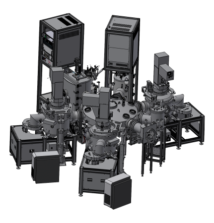
P295+501 – 4″ HV multitech. deposition cluster tool IPHT
Application
Multi chamber system as combination of HV e-beam deposition system & HV sputter deposition systems for thin film and multilayer deposition at 4″ substrates
Year of delivery
2011 (P295 part) + 2023 (Upgrade to current system)
Installation site
IPHT, Jena, Germany
Design Features
- UHV magnetron sputter deposition cluster tool with confocal sputtering configuration.
- In three sputter chambers up to four 3″ magnetrons with manual in situ tilting can be installed.
- Including a fully motorized 2 axes sample manipulators with integrated sample clamping stage, pneumatic sample shutter, RF back sputtering option installed and sample temperature stabilization (mild cooling and mild heating).
- In a fourth sputter chamber one 3″ magnetron and an griddles ion source are installed.
- Including a fully motorized 2 axes sample manipulators with integrated sample clamping stage and sample temperture stabilization (mild cooling and mild heating).
- One e-beam deposition chamber with griddles ion source and thermal treatment is part of the system too.
- Including a fully motorized 3 axes sample manipulators with integrated sample clamping stage and sample temperture stabilization (mild cooling and mild heating).
- Oxydation chamber with dynamic as well as static oxydation pressure regulation.
- Load lock chamber with motorized storage for three samples.
- Automatic sample transfer between all chambers via a radial distribution chamber.
Special Features
- At least two different sample sizes (4″ and 6″ wafer) can be handled (using different kind of sample adapters).
- Ar gas backside cooling installed at three sputter chamber sample stages.
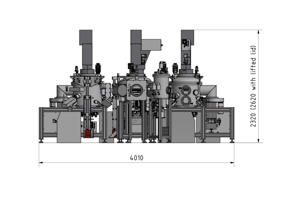
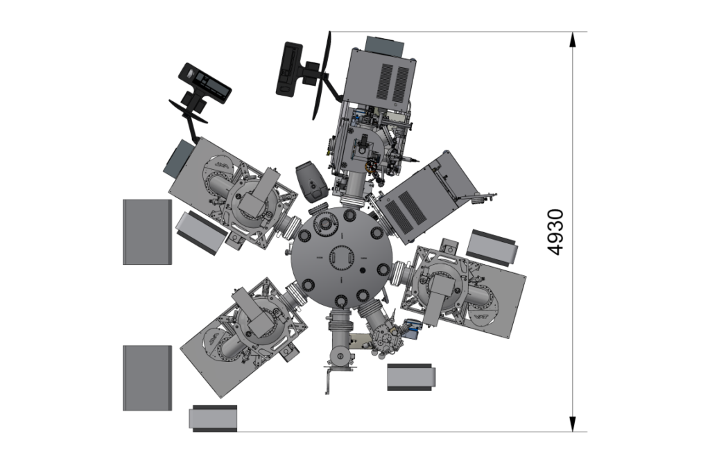
Outer Dimensions
Technical specifications and performance values
General
Sputtering chamber (SP1, SP2, SP3)
Size
About 600 mm diameter, about 720 mm height
Material
stainless steel
Sputtering chamber for granular Al (GRAL)
Size
About 410 mm diameter, about 630 mm height
Material
stainless steel
E-Beam deposition chamber for high purity Al (HPAL)
Size
About 550 mm diameter, about 1020 mm height
Material
stainless steel
Load lock chamber
Size
About 250 mm diameter, about 310 mm height
Material
stainless steel
Oxidation chamber
Size
About 300 mm diameter, about 500 mm height
Material
stainless steel
Radial distribution chamber
Size
About 1250 mm diameter, about 450 mm height
Material
stainless steel
Vacuum
Sputtering chamber (SP1, SP2, SP3)
Base pressure
< 2 * 10-8 mbar
Pump down time
1 hour to < 4 * 10-7 mbar
Chamber pumping
Cryo pumping stage, chamber lid differentially pumped by dry foreline pump
Sputtering chamber for granular Al (GRAL)
Base pressure
< 1 * 10-7 mbar
Pump down time
1 hour to < 7 * 10-7 mbar
Chamber pumping
Turbo pumping stage, chamber door differentially pumped by dry foreline pump
E-Beam deposition chamber for high purity Al (HPAL)
Base pressure
< 5 * 10-8 mbar
Pump down time
1 hour to < 4 * 10-7 mbar
Chamber pumping
Cryo pumping stage, chamber door differentially pumped by dry foreline pump
Load lock chamber
Base pressure
< 3 * 10-8 mbar
Pump down time
1 hour to < 2 * 10-7 mbar
Chamber pumping
Turbo pumping stage with dry foreline pump
Oxydation chamber
Base pressure
< 3 * 10-7 mbar
Pump down time
1 hour to < 10-6 mbar
Chamber pumping
Turbo pumping stage with dry foreline pump
Radial distribution chamber
Base pressure
< 5 * 10-8 mbar
Pump down time
1 hour to < 7 * 10-7 mbar
Chamber pumping
Turbo pumping stage with dry foreline pump
Manipulator features
Sputtering chamber (SP1, SP2, SP3)
Sample size
nominal diameter 4″ substrate
(diameter max. 6″ substrate)
Motion axes
Motorized sample roation axis
Sample clamping tool with motorized sample release unit (part of the manipulator head) for optimized thermal contact
Pneumatic sample shutter (part of the manipulator head)
Temperatures
0°C up to +100°C at sample
Special features
Sample bias and sputter cleaning (RF, DC or pulsed DC) is possible
Sputtering chamber for granular Al (GRAL)
Sample size
nominal diameter 4″ substrate
(diameter max. 6″ substrate)
Motion axes
Motorized sample roation axis
Sample clamping tool with motorized sample release unit (part of the manipulator head) for optimized thermal contact
Temperatures
0°C up to +80°C at sample
E-Beam deposition chamber for high purity Al (HPAL)
Sample size
nominal diameter 4″ substrate
(diameter max. 6″ substrate)
Motion axes
Motorized sample roation axis
Motorized sample tilting axis
Sample clamping tool with motorized sample release unit (part of the manipulator head) for optimized thermal contact
Temperatures
0°C up to +80°C at sample
Load lock chamber
(Sample storage)
Storage size
3 sample holders
Sample size
diameter max. 4″ substrate
Motion axes
motorized z translation of the sample storage stage
Sample preparation features
Sputtering chamber (SP1, SP2, SP3)
Plasma treatment / sample precleaning
Up to 5E-3 mbar partly ionised argon gas (using a RF sputter plasma at the sample)
Wide range variation of RF power
Sputtering chamber for granular Al (GRAL)
Plasma treatment
Up to 5E-4 mbar partly ionised argon gas (using a griddless ion gun)
Ion beam etching / sample precleaning
Wide range variation of ion energy and ion beam current
E-Beam deposition chamber for high purity Al (HPAL)
Plasma treatment
Up to 5E-4 mbar partly ionised argon gas (using a griddless ion gun)
Ion beam etching / sample precleaning
Wide range variation of ion energy and ion beam current
Special features
Possibility of thermal treatment at temperatures above 900°C
Oxydation chamber
Dynamic oxydation pressure (regulation)
0.01 mbar up to 1 mbar
upstream as well as downstream pressure regulation implemented
Static oxydation pressure
> 1 mbar up to 50 mbar
Special features
Gas inlet via manual dosing valve in combination with mass flow controller
Pneumatic blocking valves at both gas inlet lines installed
Performance test results
Pump down curves (Part 1)

Pump down curves (Part 2)

